
BS 6724, IEC/EN 60228, EN 50267-2-1, IEC/EN 60502-1, Flame Retardant according to IEC/EN 60332-1-2, IEC/EN 60332-3-24 Cat C Low Smoke Zero Halogen according to IEC/EN 60754-1/2, IEC/EN 61034-1/2
APPLICATION
Power and auxiliary control cables for use in power networks, underground, outdoor and indoor applications and for use in cable ducting. For installation where fire, smoke emission and toxicfumes create a potential threat to life and equipment.
STANDARDS
CHARACTERISTICS
Voltage Rating Uo/U : 0.6/1kV
Temperature Rating : Fixed: -20°C to +90°C
Minimum Bending Radius : 1.5mm² to 16mm2 - Fixed: 6 x overall diameter 25mm2 and above - Fixed: 8 x overall diameter
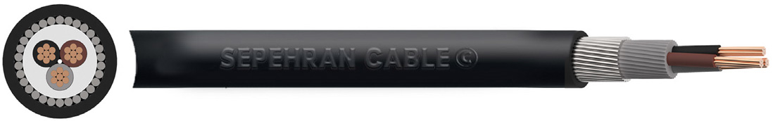
CONSTRUCTION
Conductor : Class 2 stranded copper conductor
Insulation :XLPE (Cross-Linked Polyethylene)
Filler :PVC (Polyvinyl Chloride)
Armour :Double galvanized steel tape
Sheath :PVC (Polyvinyl Chloride)
Outer Sheath:PVC (Polyvinyl Chloride)
Core Identification :2 core: Blue Black 3 core: Yellow Red Black 4 core: Yellow Red Black Blue 5 core: Yellow Red Black Blue Green/Yellow
Sheath Colour :Black
DIMENSIONS
| NO. OF CORES | NOMINAL CROSS SECTIONAL AREA mm² |
NOMINAL THICKNESS OF INSULATION mm |
NOMINAL OVERALL DIAMETER mm |
NOMINAL WEIGHT kg/km |
BW / CW GLAND | WRAPAROUND CLEATS | |
| UNDER ARMOUR | OVERALL | ||||||
| 2 | 1/5 | 0/6 | 7/3 | 12/1 | 302 | 20S | CC5 |
| 2 | 2/5 | 0/7 | 8/5 | 13/6 | 346 | 20S | CC6 |
| 2 | 4 | 0/7 | 9/4 | 14/7 | 410 | 20S | CC6 |
| 2 | 6 | 0/7 | 10/5 | 15/9 | 499 | 20 | CC7 |
| 2 | 10 | 0/7 | 12/3 | 18 | 648 | 20 | CC8 |
| 2 | 16 | 0/7 | 14/3 | 20/4 | 978 | 20 | CC9 |
| 2 | 25 | 0/9 | 14/7 | 20/4 | 1290 | 25 | CC9 |
| 2 | 35 | 0/9 | 16/8 | 23/3 | 1500 | 32 | CC10 |
| 2 | 50 | 1 | 19 | 25/8 | 1890 | 32 | CC12 |
| 2 | 70 | 1/1 | 22 | 29 | 2450 | 32 | CC12 |
| 2 | 95 | 1/1 | 25/1 | 33/1 | 3300 | 32 | CC14 |
| 2 | 120 | 1/2 | 31/1 | 39/3 | 4020 | 40 | CC16 |
| 2 | 150 | 1/4 | 30/9 | 39/3 | 4750 | 40 | CC18 |
| 3 | 1/5 | 0/6 | 7/8 | 12/6 | 330 | 20S | CC5 |
| 3 | 2/5 | 0/7 | 9/2 | 14/1 | 390 | 20S | CC6 |
| 3 | 4 | 0/7 | 10 | 15/3 | 464 | 20 | CC7 |
| 3 | 6 | 0/7 | 11/2 | 16/6 | 568 | 20 | CC7 |
| 3 | 10 | 0/7 | 13/1 | 19/5 | 866 | 20 | CC8 |
| 3 | 16 | 0/7 | 15/3 | 21/6 | 1152 | 25 | CC9 |
| 3 | 25 | 0/9 | 18/9 | 23/6 | 1800 | 25 | CC11 |
| 3 | 35 | 0/9 | 21/3 | 25/7 | 2230 | 32 | CC12 |
| 3 | 50 | 1 | 21/7 | 28/5 | 2490 | 32 | CC12 |
| 3 | 70 | 1/1 | 25/2 | 32/2 | 3290 | 32 | CC14 |
| 3 | 95 | 1/1 | 28/8 | 37 | 4440 | 40 | CC16 |
| 3 | 120 | 1/2 | 32 | 40/4 | 5470 | 40 | CC16 |
| 3 | 150 | 1/4 | 35/9 | 45/5 | 6930 | 50S | CC18 |
| 4 | 1/5 | 0/6 | 8/5 | 13/5 | 365 | 20S | CC6 |
| 4 | 2/5 | 0/7 | 9/9 | 15 | 438 | 20 | CC6 |
| 4 | 4 | 0/7 | 11 | 16/4 | 532 | 20 | CC7 |
| 4 | 6 | 0/7 | 12/3 | 18/7 | 764 | 20 | CC8 |
| 4 | 10 | 0/7 | 14/5 | 21/1 | 1013 | 25 | CC9 |
| 4 | 16 | 0/7 | 17 | 23/4 | 1360 | 25 | CC10 |
| 4 | 25 | 0/9 | 21 | 26/1 | 2160 | 32 | CC11 |
| 4 | 35 | 0/9 | 23/6 | 28/6 | 2690 | 32 | CC12 |
| 4 | 50 | 1 | 25 | 32 | 3130 | 32 | CC14 |
| 4 | 70 | 1/1 | 29/5 | 37/7 | 4500 | 40 | CC16 |
| 4 | 95 | 1/1 | 33/3 | 41/7 | 5600 | 50S | CC18 |
| 4 | 120 | 1/2 | 37/5 | 47/1 | 7400 | 50 | CC20 |
| 4 | 150 | 1/4 | 41/6 | 51/4 | 8780 | 50 | - |
| 4 | 185 | 1/6 | 46/4 | 56/6 | 10630 | 63S | - |
| 4 | 240 | 1/7 | 52/6 | 63 | 13390 | 63 | - |
| 4 | 300 | 1/8 | 56/3 | 63/6 | 14998 | 75S | - |
| 5 | 1/5 | 0/6 | 9/7 | 14/3 | 410 | 20S | CC6 |
| 5 | 2/5 | 0/7 | 11/7 | 16/3 | 470 | 20 | CC7 |
| 5 | 4 | 0/7 | 13 | 17/8 | 710 | 20 | CC7 |
| 5 | 6 | 0/7 | 14/5 | 20 | 876 | 25 | CC8 |
| 5 | 10 | 0/7 | 17/2 | 22/9 | 1165 | 25 | CC10 |
| 5 | 16 | 0/7 | 20 | 26/6 | 1742 | 32 | CC11 |
| 5 | 25 | 0/9 | 24/7 | 31/5 | 2323 | 32 | CC14 |
| 5 | 35 | 0/9 | 27/8 | 34/8 | 2932 | 40 | CC14 |
| 5 | 50 | 1 | 32/4 | 40/4 | 4192 | 50S | CC16 |
| 5 | 70 | 1/1 | 35/8 | 43 | 5500 | 50S | CC18 |
| 5 | 95 | 1/1 | 42/1 | 49 | 7145 | 50S | CC20 |
CONDUCTORS
Class 2 Stranded Conductors for Single Core and Multi-Core Cables
| NOMINAL CROSS SECTIONAL AREA mm2 |
MINIMUM NO. OF WIRES IN CONDUCTOR | MAXIMUM RESISTANCE OF CONDUCTOR AT 20ºC | |||||
| Circular | Shaped | Annealed Copper Conductor | |||||
| CU | AL | CU | AL | Plain wires ohms/km |
|||
| 1/5 | 7 | - | - | - | 12/1 | ||
| 2/5 | 7 | - | - | - | 7/41 | ||
| 4 | 7 | - | - | - | 4/61 | ||
| 6 | 7 | - | - | - | 3/08 | ||
| 10 | 7 | 7 | - | - | 1/83 | ||
| 16 | 7 | 7 | - | - | 1/15 | ||
| 25 | 7 | 7 | 6 | 6 | 0/727 | ||
| 35 | 7 | 7 | 6 | 6 | 0/524 | ||
| 50 | 19 | 19 | 6 | 6 | 0/387 | ||
| 70 | 19 | 19 | 12 | 12 | 0/268 | ||
| 95 | 19 | 19 | 15 | 15 | 0/193 | ||
| 120 | 37 | 37 | 18 | 15 | 0/153 | ||
| 150 | 37 | 37 | 18 | 15 | 0/124 | ||
| 185 | 37 | 37 | 30 | 30 | 0/0991 | ||
| 240 | 37 | 37 | 34 | 30 | 0/0754 | ||
ELECTRICAL CHARACTERISTICS XLPE/PVC/SWA/PVC
Current Carrying Capacity
| NOMINAL CROSS SECTIONAL AREA mm² |
REFERENCE METHOD C (CLIPPED DIRECT) Amps |
REFERENCE METHOD E (IN FREE AIR OR ON A PERFORATED CABLE TRAY, HORIZONTAL OR VERTICAL) Amps |
REFERENCE METHOD D (DIRECT IN GROUND OR IN DUCTING IN GROUND, IN OR AROUND BUILDINGS) Amps |
||||
| 1 Two Core Cable Single-Phase AC or DC |
1 Three or 1 Four Core Cable Three-Phase AC |
1 Two Core Cable Single-Phase AC or DC |
1 Three or 1 Four Core Cable Three-Phase AC |
1 Two Core Cable Single-Phase AC or DC |
1 Three or 1 Four Core Cable Three-Phase AC |
||
| 1/5 | 27 | 23 | 29 | 25 | 25 | 21 | |
| 2/5 | 36 | 31 | 39 | 33 | 33 | 28 | |
| 4 | 49 | 42 | 52 | 44 | 43 | 36 | |
| 6 | 62 | 53 | 66 | 56 | 53 | 44 | |
| 10 | 85 | 73 | 90 | 78 | 71 | 58 | |
| 16 | 110 | 94 | 115 | 99 | 91 | 75 | |
| 25 | 146 | 124 | 152 | 131 | 116 | 96 | |
| 35 | 180 | 154 | 188 | 162 | 139 | 115 | |
| 50 | 219 | 187 | 228 | 197 | 164 | 135 | |
| 70 | 279 | 238 | 291 | 251 | 203 | 167 | |
| 95 | 338 | 289 | 354 | 304 | 239 | 197 | |
| 120 | 392 | 335 | 410 | 353 | 271 | 223 | |
| 150 | 451 | 386 | 472 | 406 | 306 | 251 | |
| 185 | 515 | 441 | 539 | 463 | 343 | 281 | |
| 240 | 607 | 520 | 636 | 546 | 395 | 324 | |
| 300 | 698 | 599 | 732 | 628 | 446 | 365 | |
| 400 | 787 | 673 | 847 | 728 | - | - | |
Air ambient temperature: 30ºC Ground ambient temperature: 20ºC Conductor operating temperature: 90ºC
Notes 1. Where a conductor operates at a temperature exceeding 70ºC it must be ascertained that the equipment connected to the conductor is suitable for the conductor operating temperature 2. Where cables in this table are connected to equipment or accessories designed to operate at a temperature not exceeding 70ºC , the current ratings given in the equivalent table for 70ºC thermoplastic insulated cables must be used.
Voltage Drop
| NOMINAL CROSS SECTIONAL AREA mm² |
TWO CORE CABLE DC |
WO CORE CABLE SINGLE-PHASE AC mV/A/m |
THREE OR FOUR CORE CABLE THREE-PHASE AC |
||||
| 1/5 | 31 | 31 | 27 | ||||
| 2/5 | 19 | 19 | 16 | ||||
| 4 | 12 | 12 | 10 | ||||
| 6 | 7/9 | 7/9 | 6/8 | ||||
| 10 | 4/7 | 4/7 | 4 | ||||
| 16 | 2/9 | 2/9 | 2/5 | ||||
| r | x | z | r | x | z | ||
| 25 | 1/85 | 1/85 | 0/16 | 1/9 | 1/6 | 0/14 | 1/65 |
| 35 | 1/35 | 1/35 | 0/155 | 1/35 | 1/15 | 0/135 | 1/15 |
| 50 | 0/98 | 0/99 | 0/155 | 1 | 0/86 | 0/135 | 0/87 |
| 70 | 0/67 | 0/67 | 0/15 | 0/69 | 0/59 | 0/13 | 0/6 |
| 95 | 0/49 | 0/5 | 0/15 | 0/52 | 0/43 | 0/13 | 0/45 |
| 120 | 0/39 | 0/4 | 0/145 | 0/42 | 0/34 | 0/13 | 0/37 |
| 150 | 0/31 | 0/32 | 0/145 | 0/35 | 0/28 | 0/125 | 0/3 |
| 185 | 0/25 | 0/26 | 0/145 | 0/29 | 0/22 | 0/125 | 0/26 |
| 240 | 0/195 | 0/2 | 0/14 | 0/24 | 0/175 | 0/125 | 0/21 |
| 300 | 0/155 | 0/16 | 0/14 | 0/21 | 0/14 | 0/12 | 0/185 |
| 400 | 0/12 | 0/13 | 0/14 | 0/19 | 0/115 | 0/12 | 0/165 |
Conductor operating temperature: 90ºC r = Resistive Component x = Reactive Component z = Impedance Value
For cables having conductors of 16mm2 or less cross sectional area their inductances can be ignored and (mV/A/m)r values only are tabulated. For cables having conductors greater than 16mm2, cross sectional area the impedance values are given as (mV/A/m)z, together with the resistive component (mV/A/m)r and the reactive component (mV/A/m)x.