Voltage Rating Uo/U : 0.6/1kV
Temperature Rating : Fixed: -25°C to +90°C
Minimum Bending Radius : 1.5mm2 to 16mm2 - Fixed: 6 x overall diameter 25mm2 and above - Fixed: 8 x overall diameter

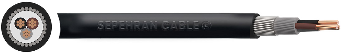
این کابل چند هسته ای روکش PVC داشته و دارای زره محافظ سیم فولادی (SWA) میباشد. این نوع کابلها جهت نصب در فضای داخلی و خارجی پروژه، در کانال های کابل حفرشده در زمین و همچنین کاربردهای زیرزمینی در شبکه های برق کاربرد دارد.
BS 5467, IEC/EN 60502-1, IEC/EN 60228 Flame Retardant according to IEC/EN 60332-1-2
Voltage Rating Uo/U : 0.6/1kV
Temperature Rating : Fixed: -25°C to +90°C
Minimum Bending Radius : 1.5mm2 to 16mm2 - Fixed: 6 x overall diameter 25mm2 and above - Fixed: 8 x overall diameter
Conductor : Class 2 stranded copper conductor
Insulation :XLPE (Cross-Linked Polyethylene)
Filler :PVC (Polyvinyl Chloride)
Armour :Double galvanized steel tape
Sheath :PVC (Polyvinyl Chloride)
Outer Sheath:PVC (Polyvinyl Chloride)
Core Identification :2 core: Blue Black 3 core: Yellow Red Black 4 core: Yellow Red Black Blue 5 core: Yellow Red Black Blue Green/Yellow
Sheath Colour :Black
| NO. OF CORES | NOMINAL CROSS SECTIONAL AREA mm2 |
NOMINAL THICKNESS OF INSULATION mm |
NOMINAL DIAMETER mm |
NOMINAL WEIGHT kg/km |
BW / CW GLAND | WRAPAROUND CLEATS | ||||||||||
| Under Armour | Overall | |||||||||||||||
| 2 | 1/5 | 0/6 | 7/3 | 12/1 | 302 | 20S | CC5 | |||||||||
| 2 | 2/5 | 0/7 | 8/5 | 13/6 | 346 | 20S | CC6 | |||||||||
| 2 | 4 | 0/7 | 9/4 | 14/7 | 410 | 20S | CC7 | |||||||||
| 2 | 6 | 0/7 | 10/5 | 15/9 | 499 | 20 | CC7 | |||||||||
| 2 | 10 | 0/7 | 12/3 | 18 | 648 | 20 | CC8 | |||||||||
| 2 | 16 | 0/7 | 14/3 | 20/4 | 978 | 20 | CC9 | |||||||||
| 2 | 25 | 0/9 | 14/7 | 20/4 | 1290 | 25 | CC9 | |||||||||
| 2 | 35 | 0/9 | 16/8 | 23/3 | 1500 | 25 | CC10 | |||||||||
| 2 | 50 | 1 | 19 | 25/8 | 1890 | 25 | CC11 | |||||||||
| 2 | 70 | 1/1 | 22 | 29 | 2450 | 32 | CC12 | |||||||||
| 2 | 95 | 1/1 | 25/1 | 33/1 | 3300 | 32 | CC14 | |||||||||
| 2 | 120 | 1/2 | 27/9 | 36/1 | 4020 | 40 | CC16 | |||||||||
| 2 | 150 | 1/4 | 30/9 | 39/3 | 4750 | 40 | CC16 | |||||||||
| 3 | 1/5 | 0/6 | 7/8 | 12/6 | 330 | 20S | CC5 | |||||||||
| 3 | 2/5 | 0/7 | 9/2 | 14/1 | 390 | 20S | CC6 | |||||||||
| 3 | 4 | 0/7 | 10 | 15/3 | 464 | 20S | CC7 | |||||||||
| 3 | 6 | 0/7 | 11/2 | 16/6 | 568 | 20 | CC7 | |||||||||
| 3 | 10 | 0/7 | 13/1 | 19/5 | 866 | 20 | CC8 | |||||||||
| 3 | 16 | 0/7 | 15/3 | 21/6 | 1152 | 25 | CC9 | |||||||||
| 3 | 25 | 0/9 | 18/9 | 23/6 | 1800 | 25 | CC11 | |||||||||
| 3 | 35 | 0/9 | 21/3 | 25/7 | 2230 | 32 | CC12 | |||||||||
| 3 | 50 | 1 | 21/7 | 28/5 | 2490 | 32 | CC12 | |||||||||
| 3 | 70 | 1/1 | 25/2 | 32/2 | 3290 | 32 | CC14 | |||||||||
| 3 | 95 | 1/1 | 28/8 | 37 | 4440 | 40 | CC16 | |||||||||
| 3 | 120 | 1/2 | 32 | 40/4 | 5470 | 40 | CC16 | |||||||||
| 3 | 150 | 1/4 | 35/9 | 45/5 | 6930 | 50S | CC18 | |||||||||
| 3 | 185 | 1/6 | 40 | 49/8 | 8350 | 63S | CC20 | |||||||||
| 3 | 240 | 1/7 | 44/9 | 55/1 | 10400 | 63S | - | |||||||||
| 3 | 300 | 1/8 | 49/8 | 60/2 | 12600 | 63S | - | |||||||||
| 3 | 400 | 2 | 55/8 | 66/6 | 14600 | 75S | - | |||||||||
| 4 | 1/5 | 0/6 | 8/5 | 13/3 | 365 | 20S | CC6 | |||||||||
| 4 | 2/5 | 0/7 | 9/9 | 15 | 438 | 20S | CC6 | |||||||||
| 4 | 4 | 0/7 | 11 | 16/4 | 532 | 20 | CC7 | |||||||||
| 4 | 6 | 0/7 | 12/3 | 18/7 | 764 | 20 | CC8 | |||||||||
| 4 | 10 | 0/7 | 14/5 | 21/1 | 1013 | 25 | CC9 | |||||||||
| 4 | 16 | 0/7 | 17 | 23/4 | 1360 | 25 | CC10 | |||||||||
| 4 | 25 | 0/9 | 21 | 26/1 | 2160 | 32 | CC11 | |||||||||
| 4 | 35 | 0/9 | 23/6 | 28/6 | 2690 | 32 | CC12 | |||||||||
| 4 | 50 | 1 | 25 | 32 | 3130 | 32 | CC14 | |||||||||
| 4 | 70 | 1/1 | 29/5 | 37/7 | 4500 | 40 | CC16 | |||||||||
| 4 | 95 | 1/1 | 33/3 | 41/7 | 5600 | 50S | CC18 | |||||||||
| 4 | 120 | 1/2 | 37/5 | 47/1 | 7400 | 50 | CC20 | |||||||||
| 4 | 150 | 1/4 | 41/6 | 51/4 | 8780 | 50 | - | |||||||||
| 4 | 185 | 1/6 | 46/4 | 56/6 | 10630 | 63S | - | |||||||||
| 4 | 240 | 1/7 | 52/6 | 63 | 13390 | 63 | - | |||||||||
| 4 | 300 | 1/8 | 58 | 68/8 | 16290 | 75S | - | |||||||||
| 4 | 400 | 2 | 65/4 | 78/1 | 19800 | 90 | - | |||||||||
| 5 | 1/5 | 0/6 | 9/7 | 14/3 | 410 | 20S | CC6 | |||||||||
| 5 | 2/5 | 0/7 | 11/7 | 16/1 | 470 | 20S | CC7 | |||||||||
| 5 | 4 | 0/7 | 13 | 17/8 | 710 | 20 | CC7 | |||||||||
| 5 | 6 | 0/7 | 14/5 | 20 | 876 | 25 | CC8 | |||||||||
| 5 | 10 | 0/7 | 17/2 | 22/9 | 1165 | 25 | CC10 | |||||||||
| 5 | 16 | 0/7 | 20 | 26/6 | 1742 | 32 | CC11 | |||||||||
| 5 | 25 | 0/9 | 24/7 | 31/5 | 2323 | 32 | CC14 | |||||||||
| 5 | 35 | 0/9 | 27/8 | 34/8 | 2932 | 40 | CC14 | |||||||||
| 5 | 50 | 1 | 32/4 | 40/4 | 4192 | 50S | CC16 | |||||||||
| NOMINAL CROSS SECTIONAL AREA mm² |
MINIMUM NO. OF WIRES IN CONDUCTOR | MAXIMUM RESISTANCE OF CONDUCTOR AT 20ºC ohms/km |
||||||||||||||
| Circular | Circular Compacted | Shaped | Annealed Copper Conductor | |||||||||||||
| Cu | Al | Cu | Al | Cu | Al | Plain Wires | ||||||||||
| 1/5 | 7 | - | 6 | - | - | - | 12/1 | |||||||||
| 2/5 | 7 | - | 6 | - | - | - | 7/41 | |||||||||
| 4 | 7 | - | 6 | - | - | - | 4/61 | |||||||||
| 6 | 7 | - | 6 | - | - | - | 3/08 | |||||||||
| 10 | 7 | 7 | 6 | 6 | - | - | 1/83 | |||||||||
| 16 | 7 | 7 | 6 | 6 | - | - | 1/15 | |||||||||
| 25 | 7 | 7 | 6 | 6 | 6 | 6 | 0/727 | |||||||||
| 35 | 7 | 7 | 6 | 6 | 6 | 6 | 0/524 | |||||||||
| 50 | 19 | 19 | 6 | 6 | 6 | 6 | 0/387 | |||||||||
| 70 | 19 | 19 | 12 | 12 | 12 | 12 | 0/268 | |||||||||
| 95 | 19 | 19 | 15 | 15 | 15 | 15 | 0/193 | |||||||||
| 120 | 37 | 37 | 18 | 15 | 18 | 15 | 0/153 | |||||||||
| 150 | 37 | 37 | 18 | 15 | 18 | 15 | 0/124 | |||||||||
| 185 | 37 | 37 | 30 | 30 | 30 | 30 | 0/0991 | |||||||||
| 240 | 37 | 37 | 34 | 30 | 34 | 30 | 0/0754 | |||||||||
| 300 | 61 | 61 | 34 | 30 | 34 | 30 | 0/0601 | |||||||||
| 400 | 61 | 61 | 53 | 53 | 53 | 53 | 0/047 | |||||||||
| NOMINAL CROSS SECTIONAL AREA mm² | REFERENCE METHOD C (CLIPPED DIRECT) Amps | REFERENCE METHOD E (IN FREE AIR OR ON A PERFORATED CABLE TRAY, HORIZONTAL OR VERTICAL) Amps | REFERENCE METHOD D (DIRECT IN GROUND OR IN DUCTING IN GROUND, IN OR AROUND BUILDINGS) Amps | ||||||||||||
|---|---|---|---|---|---|---|---|---|---|---|---|---|---|---|---|
| 1 Two Core Cable Single-Phase AC or DC | 1 Two Core Cable Single-Phase AC or DC | 1 Three or 1 Four Core Cable Three-Phase AC | 1 Two Core Cable Single-Phase AC or DC | 1 Three or 1 Four Core Cable Three-Phase AC | |||||||||||
| 1/5 | 27 | 23 | 29 | 25 | 25 | 21 | |||||||||
| 2/5 | 36 | 31 | 39 | 33 | 33 | 28 | |||||||||
| 4 | 49 | 42 | 52 | 44 | 43 | 36 | |||||||||
| 6 | 62 | 53 | 66 | 56 | 53 | 44 | |||||||||
| 10 | 85 | 73 | 90 | 78 | 71 | 58 | |||||||||
| 16 | 110 | 94 | 115 | 99 | 91 | 75 | |||||||||
| 25 | 146 | 124 | 152 | 131 | 116 | 96 | |||||||||
| 35 | 180 | 154 | 188 | 162 | 139 | 115 | |||||||||
| 50 | 219 | 187 | 228 | 197 | 164 | 135 | |||||||||
| 70 | 279 | 238 | 291 | 251 | 203 | 167 | |||||||||
| 95 | 338 | 289 | 354 | 304 | 239 | 197 | |||||||||
| 120 | 392 | 335 | 410 | 353 | 271 | 223 | |||||||||
| 150 | 451 | 386 | 472 | 406 | 306 | 251 | |||||||||
| 185 | 515 | 441 | 539 | 463 | 343 | 281 | |||||||||
| 240 | 607 | 520 | 636 | 546 | 395 | 324 | |||||||||
| 300 | 698 | 599 | 732 | 628 | 446 | 365 | |||||||||
| 400 | 787 | 673 | 847 | 728 | - | 570 | |||||||||
Air ambient temperature: 30ºC
Ground ambient temperature: 20ºC
Conductor operating temperature: 90ºC
| NOMINAL CROSS SECTIONAL AREA mm2 |
TWO CORE CABLE DC | TWO CORE CABLE SINGLE-PHASE AC mV/A/m |
THREE OR FOUR CORE CABLE THREE-PHASE AC mV/A/m |
|||||||||||||
| 1/5 | 31 | 31 | 27 | |||||||||||||
| 2/5 | 19 | 19 | 16 | |||||||||||||
| 4 | 12 | 12 | 10 | |||||||||||||
| 6 | 7/9 | 7/9 | 6/8 | |||||||||||||
| 10 | 4/7 | 4/7 | 4 | |||||||||||||
| 16 | 2/9 | 2/9 | 2/5 | |||||||||||||
| r | x | z | r | x | z | |||||||||||
| 25 | 1/85 | 1/85 | 0/16 | 1/9 | 1/6 | 0/14 | 1/65 | |||||||||
| 35 | 1/35 | 1/35 | 0/155 | 1/35 | 1/15 | 0/135 | 1/15 | |||||||||
| 50 | 0/98 | 0/99 | 0/155 | 1 | 0/86 | 0/135 | 0/87 | |||||||||
| 70 | 0/67 | 0/67 | 0/15 | 0/69 | 0/59 | 0/13 | 0/6 | |||||||||
| 95 | 0/49 | 0/5 | 0/15 | 0/52 | 0/43 | 0/13 | 0/45 | |||||||||
| 120 | 0/39 | 0/4 | 0/145 | 0/42 | 0/34 | 0/13 | 0/37 | |||||||||
| 150 | 0/31 | 0/32 | 0/145 | 0/35 | 0/28 | 0/125 | 0/3 | |||||||||
| 185 | 0/25 | 0/26 | 0/145 | 0/29 | 0/22 | 0/125 | 0/26 | |||||||||
| 240 | 0/195 | 0/2 | 0/14 | 0/24 | 0/175 | 0/125 | 0/21 | |||||||||
| 300 | 0/155 | 0/16 | 0/14 | 0/21 | 0/14 | 0/12 | 0/185 | |||||||||
| 400 | 0/12 | 0/13 | 0/14 | 0/19 | 0/115 | 0/12 | 0/165 | |||||||||
لیست محصولات افزوده شده
سبد خرید خالی !