
BS 6724, IEC/EN 60502-1, EN 60228, Low Smoke Zero Halogen according to IEC/EN 60754-1/2, IEC/EN 61034-2 Flame Retardant according to IEC/EN 60332-1-2, IEC/EN 60332-3-24 Cat C
APPLICATION
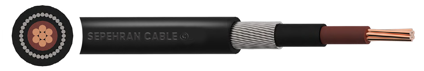
این کابل تک هسته ای روکش PVC داشته و دارای زره محافظ سیم آلومینیومی (AWA) میباشد. این نوع کابلها جهت نصب در فضای داخلی و خارجی پروژه، در کانال های کابل حفرشده در زمین و همچنین کاربردهای زیرزمینی در شبکه های برق کاربرد دارد.
STANDARDS
CHARACTERISTICS
Voltage Rating Uo/U : 0.6/1kV
Temperature Rating : Fixed: -20°C to +90°C
Minimum Bending Radius : Fixed: 8 x overall diameter
CONSTRUCTION
| Conductor : | Class 2 stranded copper conductor | |
| Insulation : | XLPE (Cross-Linked Polyethylene) | |
| Bedding : | LSZH (Low Smoke Zero Halogen) | |
| Armour : | AWA (Aluminium Wire Armour) | |
| Sheath : | LSZH (Low Smoke Zero Halogen) | |
| Sheath Colour : | Black | |
DIMENSIONS
| NO. OF CORES | NOMINAL CROSS SECTIONAL AREA mm² |
NOMINAL THICKNESS OF INSULATION mm |
NOMINAL OVERALL DIAMETER mm |
NOMINAL WEIGHT kg/km |
BW / CW GLAND | WRAPAROUND CLEATS | ||||||||||
| Under Armour | Overall | |||||||||||||||
| 1 | 50 | 1 | 12/7 | 17/5 | 800 | 20 | CC7 | |||||||||
| 1 | 70 | 1/1 | 14/7 | 20/2 | 960 | 25 | CC8 | |||||||||
| 1 | 95 | 1/1 | 16/6 | 22/3 | 1240 | 25 | CC9 | |||||||||
| 1 | 120 | 1/2 | 18/5 | 24/2 | 1510 | 25 | CC10 | |||||||||
| 1 | 150 | 1/4 | 20/8 | 27/4 | 1900 | 32 | CC11 | |||||||||
| 1 | 185 | 1/6 | 23/2 | 30 | 2320 | 32 | CC12 | |||||||||
| 1 | 240 | 1/7 | 26 | 32/8 | 2930 | 32 | CC14 | |||||||||
| 1 | 300 | 1/8 | 28/6 | 35/6 | 3580 | 40 | CC16 | |||||||||
| 1 | 400 | 2 | 32/4 | 40/5 | 4600 | 40 | CC16 | |||||||||
| 1 | 500 | 2/2 | 36 | 44/2 | 5770 | 50S | CC18 | |||||||||
| 1 | 630 | 2/4 | 40 | 48/8 | 7250 | 50 | CC20 | |||||||||
| 1 | 800 | 2/6 | 45/6 | 55/4 | 9381 | 63S | - | |||||||||
| 1 | 1000 | 2/8 | 50/6 | 60/6 | 11540 | 63S | - | |||||||||
CONDUCTORS
Class 2 Stranded Conductors for Single Core and Multi-Core Cables
| NOMINAL CROSS SECTIONAL AREA mm² |
MINIMUM NO. OF WIRES IN CONDUCTOR | MAXIMUM RESISTANCE OF CONDUCTOR AT 20ºC ohms/km |
||||||||||||||
| Circular | Circular Compacted | Shaped | Annealed Copper Conductor | |||||||||||||
| Cu | Al | Cu | Al | Cu | Al | Plain Wires | ||||||||||
| 50 | 19 | 19 | 6 | 6 | 6 | 6 | 0/387 | |||||||||
| 70 | 19 | 19 | 12 | 12 | 12 | 12 | 0/268 | |||||||||
| 95 | 19 | 19 | 15 | 15 | 15 | 15 | 0/193 | |||||||||
| 120 | 37 | 37 | 18 | 15 | 18 | 15 | 0/153 | |||||||||
| 150 | 37 | 37 | 18 | 15 | 18 | 15 | 0/124 | |||||||||
| 185 | 37 | 37 | 30 | 30 | 30 | 30 | 0/0991 | |||||||||
| 240 | 37 | 37 | 34 | 30 | 34 | 30 | 0/0754 | |||||||||
| 300 | 61 | 61 | 34 | 30 | 34 | 30 | 0/0601 | |||||||||
| 400 | 61 | 61 | 53 | 53 | 53 | 53 | 0/047 | |||||||||
| 630 | 91 | 91 | 53 | 53 | 53 | 53 | 0/0283 | |||||||||
| 800 | 91 | 91 | 53 | 53 | - | - | 0/0221 | |||||||||
| 1000 | 91 | 91 | 53 | 53 | - | - | 0/0176 | |||||||||
ELECTRICAL CHARACTERISTICS XLPE/LSZH/AWA/LSZH
Current Carrying Capacity
| NOMINAL CROSS SECTIONAL AREA mm² |
REFERENCE METHOD C (CLIPPED DIRECT) Amps |
REFERENCE METHOD F (IN FREE AIR OR ON A PERFORATED CABLE TRAY, HORIZONTAL OR VERTICAL) Amps |
||||||||||||||
| 2 Cables Single- Phase AC or DC Flat |
3 or 4 Cables Three-Phase AC Flat | 2 Cables Single-Phase AC or DC Flat | 3 Cables Three-Phase AC Flat | 3 Cables Three-Phase AC Trefoil | 2 Cables DC | 2 Cables Single-Phase AC |
3 or 4 Cables Three-Phase AC | |||||||||
| Horizontal | Vertical | Horizontal | Vertical | Horizontal | Vertical | |||||||||||
| 50 | 237 | 220 | 253 | 232 | 222 | 284 | 270 | 282 | 266 | 288 | 266 | |||||
| 70 | 303 | 277 | 322 | 293 | 285 | 356 | 349 | 357 | 337 | 358 | 331 | |||||
| 95 | 367 | 333 | 389 | 352 | 346 | 446 | 426 | 436 | 412 | 425 | 393 | |||||
| 120 | 425 | 383 | 449 | 405 | 402 | 519 | 497 | 504 | 477 | 485 | 449 | |||||
| 150 | 488 | 437 | 516 | 462 | 463 | 600 | 575 | 566 | 539 | 549 | 510 | |||||
| 185 | 557 | 496 | 587 | 524 | 529 | 688 | 660 | 643 | 614 | 618 | 574 | |||||
| 240 | 656 | 579 | 689 | 612 | 625 | 815 | 782 | 749 | 714 | 715 | 666 | |||||
| 300 | 755 | 662 | 792 | 700 | 720 | 943 | 906 | 842 | 805 | 810 | 755 | |||||
| 400 | 853 | 717 | 899 | 767 | 815 | 1137 | 1094 | 929 | 889 | 848 | 797 | |||||
| 500 | 962 | 791 | 1016 | 851 | 918 | 1314 | 1266 | 1032 | 989 | 923 | 871 | |||||
| 630 | 1082 | 861 | 1146 | 935 | 1027 | 1528 | 1474 | 1139 | 1092 | 992 | 940 | |||||
| 800 | 1170 | 904 | 1246 | 987 | 1119 | 1809 | 1744 | 1204 | 1155 | 1042 | 978 | |||||
| 1000 | 1261 | 961 | 1345 | 1055 | 1214 | 2100 | 2026 | 1289 | 1238 | 1110 | 1041 | |||||
Ambient temperature: 30ºC
Conductor operating temperature: 90ºC
Notes
1. Where a conductor operates at a temperature exceeding 70ºC it must be ascertained that the equipment connected to the conductor is suitable for the conductor operating temperature
2. Where cables in this table are connected to equipment or accessories designed to operate at a temperature not exceeding 70ºC , the current ratings given in the equivalent table for 70ºC thermoplastic insulated cables
VOLTAGE DROP
| NOMINAL CROSS SECTIONAL AREA mm² |
TWO CORE CABLE DC | REFERENCE METHOD C & F (CLIPPED DIRECT, ON TRAY OR IN FREE AIR) mV/A/m |
||||||||||||||
| 2 Cables Single-Phase AC | 3 or 4 Cables Three-Phase AC | |||||||||||||||
| Touching | Spaced* | Trefoil and Touching | Flat and Touching | Flat and Spaced* | ||||||||||||
| r | x | z | r | x | z | r | x | z | r | x | z | r | x | z | ||
| 50 | 0/98 | 0/99 | 0/21 | 1 | 0/98 | 0/29 | 1 | 0/86 | 0/18 | 0/87 | 0/84 | 0/25 | 0/88 | 0/84 | 0/33 | 0/9 |
| 70 | 0/67 | 0/68 | 0/2 | 0/71 | 0/69 | 0/29 | 0/75 | 0/59 | 0/17 | 0/62 | 0/6 | 0/25 | 0/65 | 0/62 | 0/32 | 0/7 |
| 95 | 0/49 | 0/51 | 0/195 | 0/55 | 0/53 | 0/28 | 0/6 | 0/44 | 0/17 | 0/47 | 0/46 | 0/24 | 0/52 | 0/49 | 0/31 | 0/58 |
| 120 | 0/39 | 0/41 | 0/19 | 0/45 | 0/43 | 0/27 | 0/51 | 0/35 | 0/165 | 0/39 | 0/38 | 0/24 | 0/44 | 0/41 | 0/3 | 0/51 |
| 150 | 0/31 | 0/33 | 0/185 | 0/38 | 0/36 | 0/27 | 0/45 | 0/29 | 0/16 | 0/33 | 0/31 | 0/23 | 0/39 | 0/34 | 0/29 | 0/45 |
| 185 | 0/25 | 0/27 | 0/185 | 0/33 | 0/3 | 0/26 | 0/4 | 0/23 | 0/16 | 0/28 | 0/26 | 0/23 | 0/34 | 0/29 | 0/29 | 0/41 |
| 240 | 0/195 | 0/21 | 0/18 | 0/28 | 0/24 | 0/26 | 0/35 | 0/18 | 0/155 | 0/24 | 0/21 | 0/22 | 0/3 | 0/24 | 0/28 | 0/37 |
| 300 | 0/155 | 0/17 | 0/175 | 0/25 | 0/195 | 0/25 | 0/32 | 0/145 | 0/15 | 0/21 | 0/17 | 0/22 | 0/28 | 0/2 | 0/27 | 0/34 |
| 400 | 0/115 | 0/145 | 0/17 | 0/22 | 0/18 | 0/24 | 0/3 | 0/125 | 0/15 | 0/195 | 0/16 | 0/21 | 0/27 | 0/2 | 0/27 | 0/33 |
| 500 | 0/093 | 0/125 | 170 | 0/21 | 0/165 | 0/24 | 0/29 | 0/105 | 0/145 | 0/18 | 0/145 | 0/2 | 0/25 | 0/19 | 0/24 | 0/31 |
| 630 | 0/073 | 0/105 | 0/165 | 0/195 | 0/15 | 0/23 | 0/27 | 0/092 | 0/145 | 0/17 | 0/135 | 0/195 | 0/24 | 0/175 | 0/23 | 0/29 |
| 800 | 0/056 | 0/09 | 0/16 | 0/19 | 0/145 | 0/23 | 0/27 | 0/086 | 0/14 | 0/165 | 0/13 | 0/18 | 0/23 | 0/175 | 0/195 | 0/26 |
| 1000 | 0/045 | 0/092 | 0/155 | 0/18 | 0/14 | 0/21 | 0/25 | 0/08 | 0/135 | 0/155 | 0/125 | 0/17 | 0/21 | 0/165 | 0/18 | 0/24 |
Conductor operating temperature: 90ºC
r = Resistive Component
x = Reactive Component
z = Impedance Value
* Spacings larger than one cable diameter will result in a larger voltage drop.
For cables having conductors of 16mm2 or less cross sectional area their inductances can be ignored and (mV/A/m)r values only are tabulated. For cables having
conductors greater than 16mm2, cross sectional area the impedance values are given as (mV/A/m)z, together with the resistive component (mV/A/m)r and the reactive
component (mV/A/m)x